|
|
|

ISOMET声光调制器, 声光偏转器, 声光移频器, AOTF, 声光可调谐滤波器
ISOMET公司主要生产各种声光器件,包括声光调制器, 声光偏转器, 声光移频器, AOTF, 声光可调谐滤波器。
声光调制器件由声光介质和压电换能器构成。当驱动源的某种特定载波频率驱动换能器时,换能器即产生同一频率的超声波并传入声光介质,在介质内形成折射率变化,光束通过介质时即发生相互作用而改变光的传播方向即产生衍射。声光调制是一种外调制技术,通常把控制激光束强度变化的声光器件称作声光调制器。声光调制技术比光源的直接调制技术有高得多的调制频率;与电光调制技术相比,它有更高的消光比(一般大于1000:1),更低的驱动功率,更优良的温度稳定性和更好的光点质量以及低的价格;与机械调制方式相比,它有更小的体积、重量和更好的输出波形。
All AO devices feature a piezo-electric transducer bonded to one face of a crystal material. When an RF drive signal is applied to this transducer, a travelling acoustic wave is generated in the crystal. Due to the photo-elastic effect the acoustic column produces a periodic change in the refractive index, similar in effect to the slits of a diffraction grating. Practical AO devices are designed such that a high proportion of the incident laser light is diffracted into a single output order. This is operation in the Bragg regime.
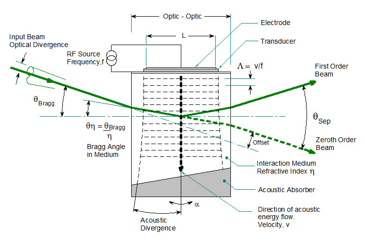
Bragg diffraction requires a defined interaction length (L), and the laser light to be input at a specific angle. The Bragg and separation angles are a function of the optical wavelength, the RF drive frequency and the crystal acoustic velocity (V). Some AO crystal types require the input beam to be polarized.
The RF drive frequency determines the output angle of the diffracted beam and the RF power determines the beam intensity. These are the basic control mechanisms of AO modulators and deflectors.
声光调制器 Acousto-optics Modulators
Acousto-optic modulators (AOM) are used to control laser beam intensity.
This can be simple ON:OFF modulation for fast switching or variable level modulation to provide proportional intensity control. These modes are determined by the RF driver type; digital or analog modulation respectively (or a combination of both).
The RF drive frequency is typically fixed and the RF amplitude is modulated accordingly.
The optical rise and fall time is defined by the laser beam diameter in the AOM and the crystal acoustic velocity. For high modulation rates, the beam will need to be focused at the AOM.
Model |
Crystal Material |
Active App(mm) |
Typical Risetime (ns) |
Typical Modulation Freq. (MHz) |
Center Freq. (MHz) |
Suggested Driver
Fixed or Variable Frequency |
Feature |
Single Beam Modulators: UV - Blue |
| M1062-FS40L-5.5 |
Fused Silica |
5.5 |
600 |
0.6 |
40 |
Fixed / Variable |
|
| M1211-aQ110-5U |
Quartz |
5 |
570 |
0.6 |
110 |
Fixed / Variable |
Low WF Distortion |
| M1211-aQ150-3U |
Quartz |
2.7 |
230 |
1.5 |
150 |
Fixed / Variable |
Low WF Distortion |
| M1212-aQ150-2 |
Quartz |
2 |
113 |
6 |
150 |
Fixed / Variable |
UV |
| M1134-FS80L |
Fused Silica |
3 |
109 |
3 |
80 |
Fixed / Variable |
|
| M1136B-FS80L-H |
Fused Silica |
2001/2/3 |
108 |
10 |
80 |
Fixed / Variable |
|
| M1088-FS110L |
Fused Silica |
3 |
109 |
3 |
110 |
Fixed / Variable |
UV |
| M1133U-aQ110L |
Quartz |
1 |
57 |
6 |
110 |
Fixed / Variable |
UV |
| M1211-aQ150-2U |
Quartz |
2 |
57 |
6 |
150 |
Fixed / Variable |
UV |
| 1206C-2-1002 |
TeO2 |
2 |
30 |
12 |
110 |
Fixed / Variable |
NUV, VIS |
| M1211-aQ150-2U |
Quartz |
2 |
25 |
14 |
150 |
Fixed / Variable |
UV |
| M1212-aQ175 |
Quartz |
1 |
20 |
18 |
175 |
Fixed / Variable |
UV |
| 1206C-833 |
TeO2 |
1 |
15 |
25 |
110 |
Fixed / Variable |
NUV, VIS |
| M1212-aQ200 |
Quartz |
0.8 |
10 |
30 |
175 |
Fixed / Variable |
UV |
| 1250C-829A |
TeO2 |
0.45 |
9 |
40 |
260 |
Fixed / Variable |
NUV, VIS |
|
Single Beam Modulators: Blue - Red |
| OAM1020 |
TeO2 (S) |
3 |
2000 |
0.2 |
110 |
Fixed / Variable |
|
| OAM1060 |
TeO2 (S) |
2 |
1000 |
0.3 |
80 |
Fixed / Variable |
|
| M1115-FS80L-3 |
Fused Silica |
3(H)x14(W) |
170 |
2 |
80 |
Fixed / Variable |
|
| M1133-aQ80L |
Quartz |
1.5 / 2 |
114 |
3 |
80 |
Fixed / Variable |
|
| M1201E-SF40-1.7 |
Glass |
1.7 |
46 |
8 |
40 |
Fixed / Variable |
|
| 1205C-x |
PbMo04 |
2001/2/3 |
25 |
15 |
80 |
Fixed / Variable |
|
| M1211-aQ110-3 |
Quartz |
2.7 |
57 |
6 |
110 |
Fixed / Variable |
Low WF Distortion |
| 1206C |
PbMo04 |
1 |
15 |
25 |
110 |
Fixed / Variable |
|
| 1206C-833 |
TeO2 |
1 |
15 |
25 |
110 |
Fixed / Variable |
|
| 1206C-2-1002 |
TeO2 |
2 |
30 |
12 |
110 |
Fixed / Variable |
|
| 1250C |
PbMo04 |
0.75 |
10 |
40 |
200 |
Fixed / Variable |
|
| 1250C-829A |
TeO2 |
0.45 |
9 |
40 |
260 |
Fixed / Variable |
|
| 1250C-848 |
TeO2 |
0.5 |
7 |
50 |
200 |
Fixed / Variable |
|
| 1250C-974 |
TeO2 |
0.4 |
7 |
50 |
200 |
Fixed / Variable |
|
| M1067-T200L |
TeO2 |
0.2 |
7 |
50 |
200 |
Fixed / Variable |
|
| 1260C |
TeO2 |
0.2 |
6 |
100 |
350 |
Fixed / Variable |
|
|
Single Beam Modulators: NIR |
| M1312-T80L |
TeO2 |
6 |
700 |
0.5 |
80 |
Fixed / Variable |
Hi Pwr |
| 1202-4 |
Glass |
4 x 14(W) |
350 |
1 |
40 |
Fixed / Variable |
|
| 1203-3 |
Fused Silica |
3 x 14(W) |
350 |
1 |
60 |
Fixed / Variable |
|
| M1099-T80L |
TeO2 |
3 |
300 |
1.2 |
80 |
Fixed / Variable |
|
| M1135-T80L |
TeO2 |
3 |
300 |
1.2 |
80 |
Fixed / Variable |
Hi Pwr |
| M1137-SF40L |
Glass |
1.5 |
191 |
2 |
40 |
Fixed / Variable |
|
| M1133-aQ80L |
Quartz |
1 |
114 |
3 |
80 |
Fixed / Variable |
|
| M1201E-SF40-1.7 |
Glass |
1.7 |
90 |
4 |
40 |
Fixed / Variable |
|
| M1080-T80L |
TeO2 |
1.5 |
80 |
4 |
80 |
Fixed / Variable |
|
| 1205C-1023 |
PbMo04 |
0.6 |
50 |
7 |
80 |
Fixed / Variable |
|
| M1142-SF80L |
Glass |
0.5 |
40 |
10 |
80 |
Fixed / Variable |
|
| 1205C-x-NIR |
PbMo04 |
0.5 |
30 |
12 |
80 |
Fixed / Variable |
|
| 1205C-843 |
PbMo04 |
0.5 |
25 |
15 |
80 |
Fixed / Variable |
|
| 1206C-NIR |
PbMo04 |
1 |
20 |
18 |
110 |
Fixed / Variable |
|
| 1250C-868 |
TeO2 |
0.5 |
15 |
23 |
150 |
Fixed / Variable |
|
| 1250C-NIR |
PbMo04 |
0.75 |
12 |
30 |
200 |
Fixed / Variable |
|
|
Single Beam Modulators: Mid IR - IR |
| 1210-G(fc)-H-MIR |
Ge |
2,4 |
240 |
10 |
60- 105 |
Fixed / Variable |
|
| M1208-G80-4-MIR |
Ge |
4x8 |
500 |
10 |
80 |
Fixed / Variable |
New version of 1208-6-4-MIR |
| M1189-G40-4 |
Ge |
4 |
470 |
0.7 |
40 |
Fixed / Variable |
|
| M1208-G40-3 |
Ge |
3x8 |
350 |
1 |
40 |
Fixed / Variable |
New version of 1208-4-955M |
| 1209-7-1064M |
Ge |
7x14 |
830 |
0.4 |
40 |
Fixed / Variable |
|
| 1209-7-1112M |
Ge |
7x14 |
830 |
0.4 |
40 |
Fixed / Variable |
|
| 1209-9-1010M |
Ge |
9x20 |
940 |
0.4 |
40 |
Fixed / Variable |
|
| AOM650-H |
Ge |
7,8,9x30 |
830 |
0.4 |
50 |
Fixed / Variable |
|
| AOM640-H |
Ge |
7,8,9x30 |
830 |
0.4 |
40 |
Fixed / Variable |
|
| AOM740-H |
Ge |
7,8,9x30 |
830 |
0.4 |
40 |
Fixed / Variable |
|
| M1199-G40-H |
Ge |
7,8,9x30 |
700 |
0.5 |
40 |
Fixed / Variable |
Pulsed lasers |
| M1310-G40-H |
Ge |
7,8,9x30 |
700 |
0.5 |
40 |
Fixed / Variable |
Pulsed lasers |
| M1315-G40 |
Ge |
6,7,8,9x15 |
700 |
0.5 |
40 |
Fixed / Variable |
|
| M1192-G40-12 |
Ge |
12 x 30 |
1200 |
0.3 |
40 |
Fixed / Variable |
Large aperture |
|
Dual Beam Modulators |
| AOM650-9 |
Ge |
9 x 30 |
600 |
0.6 |
40 / 60 |
|
|
| M1199-G50-9 |
Ge |
9 x 30 |
600 |
0.6 |
40 / 60 |
|
Pulsed lasers |
| DBM1172-G41-9 |
Ge |
9 x 20 |
600 |
0.6 |
43 / -43 |
|
|
| DBM1186-G54-9 |
Ge |
9 x 20 |
600 |
0.6 |
54 / -54 |
|
|
| DBM1199-G54-9 |
Ge |
9 x 20 |
600 |
0.6 |
54 / -54 |
|
|
|
Multichannel Modulators |
Model |
Channels |
Material |
Active Aperture (mm) |
Typical Risetime (ns) |
Information Bandwidth (MHz) |
Center Freq. (MHz) |
Feature |
| M1140 |
4 |
PbMoO4 |
0.7 |
25 |
15 |
110 |
|
| G7060 |
6 |
Ge |
0.8 |
70 |
5 |
70 |
|
| M8080 |
8 |
PbMoO4 |
0.5 |
55 |
6 |
80 |
|
| M9080C |
8 |
PbMoO4 |
0.7 |
36 |
9 |
90 |
colinear o/p |
| M15080 |
8 |
Quartz |
0.7 |
70 |
5 |
110 |
|
|
Modulators with Integrated Driver |
| Model |
Std A/R |
Optical Material |
Max Aperture (mm) |
Typical Risetime (ns) |
Typical Modulation Freq. (MHz) |
Center Freq. (MHz) |
Mod |
| IMAD-P80L |
VIS |
PbMo04 |
1.5 |
25 |
15 |
80 |
Analog |
| IMDD-P80L |
VIS |
PbMo04 |
1.5 |
25 |
15 |
80 |
Digital |
| IMAD-T110L |
405nm |
TeO2 |
1.5 |
25 |
15 |
110 |
Analog |
| IMDD-T110L |
405nm |
TeO2 |
1.5 |
25 |
15 |
110 |
Digital |
| IMAA-P80L |
VIS |
PbMo04 |
1.5 |
25 |
15 |
80 |
Amp Only |
声光移频器 Frequency Shifters
All AO devices apply a frequency shift to the diffracted output beams. Acousto-optic frequency shifters (AOFS) are compact devices designed specifically for this task. Depending on the selected Bragg angle, these devices will either up-shift or down-shift the laser light by the frequency of the applied RF signal. Two or more devices can be cascaded in order to achieve sum or difference frequency combinations. Compound absorber angles are incorporated to minimize acoustic reflections.
Model |
Std A/R |
Crystal Material |
Active App (mm) |
Centre Freq(MHz) |
Tuning BW (MHz) |
Suggested Driver Fixed or Variable Frequency |
Feature |
| OAM1059-V31 |
633nm |
TeO2 (S) |
1.5 |
+/-10 |
+/- 0.5 |
Fixed / Variable |
+ and - shift |
| OAM1059A |
633nm |
TeO2 (S) |
1.5 |
15 |
+/- 1.0 |
Fixed / Variable |
|
| FS1303-TxxxR-J2 |
NIR |
TeO2 (S) |
2 |
xxx |
+/- 1.0 |
Fixed / Variable |
|
| OAM1141-TxxS-2 |
633nm |
TeO2 (S) |
2 |
40 / 80 |
+/- 1.0 |
Fixed / Variable |
|
| M1136A-FS40S-1 |
UV |
FS (S) |
1 |
40 |
+/- 5 |
Fixed / Variable |
|
| 1205C-1-869 |
633nm |
PbMo04 |
0.7 |
80 |
+/- 15 |
Fixed / Variable |
|
| 1205-1054 |
VIS |
PbMo04 |
1 |
80 |
+/- 5 |
Fixed / Variable |
|
| M1141-P80-1 |
VIS |
PbMo04 |
1 |
80 |
+/- 5 |
Fixed / Variable |
|
| 1205-1118 |
VIS,NIR |
PbMo04 |
2 |
80 |
+/- 5 |
Fixed / Variable |
|
| M1136B-FS80L-H |
UV |
FS (L) |
1/2/3 |
80 |
+/- 5 |
Fixed / Variable |
|
| 1206C |
VIS,NIR |
PbMo04 |
1 |
110 |
+/- 25 |
Fixed / Variable |
|
| 1205-1069 |
VIS |
PbMo04 |
1 |
160 |
+/- 5 |
Fixed / Variable |
|
| 1250C |
VIS,NIR |
PbMo04 |
0.75 |
200 |
+/- 50 |
Fixed / Variable |
|
| 1250C-829A |
NUV,VIS |
TeO2 |
0.45 |
260 |
+/- 50 |
Fixed / Variable |
|
| OPP-1 |
VIS |
PbMoO4 |
1.5 |
300 |
+/- 100 |
Fixed / Variable |
|
| 1260C |
NUV,VIS |
TeO2 |
0.2 |
350 |
+/- 100 |
Fixed / Variable |
|
| 1209-7-1064M |
IR |
Ge |
6 |
40 |
+/- 10 |
Fixed / Variable |
|
| 1210-G-(fc)-H-MIR |
Mid-IR |
Ge |
2,4 |
60 / 105 |
+/- 10 |
Fixed / Variable |
|
| M1208-G80-3 |
IR |
Ge |
3 |
80 |
+/- 2.5 |
Fixed / Variable |
|
声光偏转器 Deflectors
AO deflectors can be used to scan a laser beam. This is achieved by changing the RF drive frequency. Random position, continuous line scans and sequential spot deflection are all possible. Scan rates in excess of 250KHz can be achieved depending on the crystal, wavelength and beam size.
Optimum efficiency requires that the input laser beam is set at the Bragg angle which is a function of the drive frequency. When swept to scan the laser beam there will be Bragg angle mismatch since the AOD can only be optically aligned at one drive frequency. In general this will cause a reduction in efficiency depending on the scan range. Several techniques may be used to minimize this effect:
- Off-axis AO deflectors (“OAD”) minimize the Bragg angle - frequency sensitivity by exploiting non-linear characteristics of birefringent crystals.
- Beam steered AO deflectors (“-BS”) electronically steer the acoustic column inside the crystal depending on the RF drive frequency. This requires a phased array electrode on the transducer with 2 or 4 RF inputs.
Model |
A/R Coating |
Material |
Rayleigh Res'n 1 2 |
Aperture (mm) |
Sweep BW (MHz) |
Center Freq. (MHz) |
Feature |
Deflectors UV - Blue |
| D1211-aQ110-5 |
UV |
Quartz |
70 |
5 x 10 |
40 |
110 |
|
| D1340-XY-aQ110-5 |
UV |
Quartz |
35 x 35 |
5 x 5 |
40 |
110 |
Dual Axis |
| D1155-T75S |
405nm |
TeO2 (S) |
140 |
9 |
10 |
75 |
|
| 1206C-2-1002 |
NUV, VIS |
TeO2 |
100 |
2 x 9 |
50 |
110 |
|
|
Deflectors Blue - Red |
| 1205C-2-804B |
VIS |
PbMoO4 |
66 |
2 x 6 |
30 |
80 |
|
| LS55-V |
VIS |
TeO2 (S) |
450 |
2 x 7 |
40 |
80 |
|
| LS110A-VIS |
VIS |
TeO2 (S) |
1100 |
4 x 14 |
50 |
100 |
|
| LS110A-VIS-XY |
VIS |
TeO2 (S) |
750x750 |
9 x 9 |
50 |
100 |
Dual Axis |
| OAD948 |
488nm |
TeO2 (S) |
600 |
3 x 8 |
50 |
100 |
|
| OAD1020 |
532nm |
TeO2 (S) |
600 |
2 x 8 |
50 |
100 |
|
| 1206C-2-1002 |
NUV, VIS |
TeO2 |
77 |
2 x 8 |
50 |
110 |
|
| OPP834 |
VIS |
PbMoO4 |
520 |
0.7 x 19 |
100 |
200 |
|
| 1250C-BS-960A |
VIS |
PbMoO4 |
160 |
1.5 x 6 |
120 |
190 |
|
| D1135-T180L |
VIS |
TeO2 |
95 |
3 x 8 |
50 |
175 |
|
|
Deflectors - Near IR |
| OAD1550-XY |
1550nm |
TeO2 (S) |
200 x 200 |
7 x 7 |
20 |
40 |
|
| LS110A-NIR |
NIR |
TeO2 (S) |
550 |
4 x 14 |
25 |
50 |
|
| LS110A-NIR-XY |
NIR |
TeO2 (S) |
240 x 240 |
6 x 6 |
25 |
50 |
|
| 1205C-x-804B |
NIR |
PbMoO4 |
66 |
2 x 6 |
40 |
80 |
|
| OAD1121-XY |
810nm |
TeO2 (S) |
500 x 500 |
9 x 9 |
40 |
80 |
|
| LS55-NIR |
NIR |
TeO2 (S) |
450 |
2 x 7 |
40 |
80 |
|
| D1312-T80L |
NIR |
TeO2 |
40 |
6 |
30 |
80 |
|
| D1086-T110L |
NIR |
TeO2 |
95 |
3 x 8 |
50 |
110 |
Conduction cooled |
| D1135-T110L |
NIR |
TeO2 |
95 |
3 x 8 |
50 |
110 |
|
| 1250-BS-926 |
NIR |
PbMoO4 |
60 |
0.5 x 3 |
70 |
145 |
|
| 1250C-BS-943A |
NIR |
PbMoO4 |
190 |
2 x 6 |
120 |
185 |
|
|
Deflectors Mid IR - IR |
| 1209-7BS-986 |
IR |
Ge |
50 |
7 x 14 |
20 |
40 |
|
| D1315-G50-H |
IR |
Ge |
70 |
7 x 20 |
20 |
50 |
|
| AOM650-H |
IR |
Ge |
100 |
7 x 30 |
20 |
50 |
|
| D1199-G50 |
IR |
Ge |
100 |
7 x 20 |
20 |
50 |
|
| D1208-XY-50-3 |
IR |
Ge |
10 x 10 |
3 x 3 |
40 |
70 |
|
| LS700-1011 |
IR |
Ge |
436 |
10 x 60 |
40 |
70 |
|
可调滤光片Tunable Filters
Acousto-optic diffraction requires momentum matching between light and sound (acoustic) waves in the crystal material. For the AO laser beam modulator, momentum matching is maximized when the input beam is aligned at the Bragg angle. AOTF applications are different. Unlike the modulator case, AOTF’s are frequently used with non-coherent, poorly collimated light and require large apertures with wide acceptance angles. To accommodate these demands, AOTF’s utilize non-linear properties of birefringent crystals. The crystal orientation and acoustic launch angle are designed such that diffraction occurs over a very narrow wavelength range for a very specific RF frequency. In fact it is so specific that multiple simultaneous frequencies can be applied to an AOTF without excessive intermodulation. This allows controlled wavelength mixing.
The acoustic launch angle and incident angle are related by design and together define the AOTF characteristics.
Model |
Spectral Range (um) |
Active Aperture (sq. mm) |
Acceptance Angle (Deg.) |
Optical BW (nm) |
Drive Frequency (MHz) |
Visible Tunable Filters |
| AOLF615-1049 |
VIS |
2.5x2.5 |
3.5 - 4.5 |
1.0 - 6.0 |
109 - 65 |
| AOLF615-1082 |
VIS |
2.5x2.5 |
3.5 - 4.5 |
1.0 - 6.0 |
109 - 65 |
| AOTF614-08 |
VIS,NIR |
5x5 |
3.5 - 6.0 |
1.0 - 22.0 |
140 - 35 |
| AOTF614-16 |
VIS,NIR |
5x5 |
2.5 - 4.2 |
0.6 - 11.0 |
140 - 35 |
| AOTF614-24 |
VIS,NIR |
5x5 |
3.5 - 6.0 |
0.4 - 7.0 |
140 - 35 |
| AOTF1331 |
mid-IR |
7x7 |
5 |
30 - 50 |
24 - 39 |
| AOTF1110-VB |
VIS,NIR |
10x10 |
5.7 (nominal) |
Variable |
80 - 50 |
|
NIR - IR Tunable Filters |
| AOTF614-08 |
VIS,NIR |
5x5 |
3.5 - 6.0 |
1.0 - 22.0 |
140 - 35 |
| AOTF614-16 |
VIS,NIR |
5x5 |
2.5 - 4.2 |
0.6 - 11.0 |
140 - 35 |
| AOTF614-24 |
VIS,NIR |
5x5 |
3.5 - 6.0 |
0.4 - 7.0 |
140 - 35 |
| AOTF920-14 |
NIR |
5x5 |
3.4 - 6.1 |
2.0 - 27.0 |
95 - 26 |
| AOTF920-20 |
NIR |
5x5 |
2.6 - 4.9 |
1.5 - 18.5 |
95 - 26 |
| AOTF920-24 |
NIR |
5x5 |
2.8 - 5.0 |
1.0 - 15.5 |
95 - 26 |
| AOTF1331 |
mid-IR |
7x7 |
5 |
30 - 50 |
24 - 39 |
| AOTF1550-SLS |
1550nm |
3x3 |
- |
2 |
81 - 84 |
| AOTF1110-VB |
VIS,NIR |
10x10 |
5.7 (nominal) |
Variable |
80 - 50 |
Q-Switches
Q-switches are intracavity devices used to generate very high peak power, short duration laser pulses. These are typically loss modulators operating on the zero order beam. The goal of a Q-switch is to diffract as much power from the zero order as possible to increase the cavity loss and extinguish the laser output. When the RF drive to the Q-switch is momentarily turned off, the optical power built up in the laser is emitted as a short pulse. The process may be repeated at rates in excess of 100KHz. Depending on the frequency and interaction length, AO Q-switches either operate in the Bragg regime, just like an AOM, with predominately a single diffracted beam or in the Raman-Nath regime with multiple diffracted beams.
Model |
Cooling |
Centre Frequency (MHz) |
Material |
Active Aperture (mm) |
Max Power (W) |
Damage Thresh (MW/cm^2) |
Driver |
| Q1072-SF24L |
Conduction |
24 |
SF10 |
1.5 |
5 |
>300 |
AQS |
| Q1058C-SFxxL-H |
Conduction |
24/27 |
SF10 |
1.0/1.5 |
5 |
>300 |
AQS |
| Q1025-TxxL-H |
Conduction |
27/80 |
TeO2 |
1 |
3 |
>250 |
AQS |
| Q1025-SFxxL-H |
Conduction |
41/80 |
SF10 |
1 |
3 |
>300 |
AQS |
| Q1080C-TxxL-H |
Conduction |
41/ 68 / 80 |
TeO2 |
1.5 |
4 |
>250 |
AQS |
| Q1087-aQ80L |
Conduction |
80 |
Quartz |
1 |
6 |
>500 |
AQS |
| Q1137-SFxxL-H |
Conduction |
41/80 |
SF57 |
1.0 / 1.5 |
6 |
>300 |
AQS |
| Q1162-SFxxL-H |
Conduction |
41/80 |
SF10 |
1 |
6 |
>300 |
AQS |
| Q1119-aQxxL-H |
Conduction |
41/ 80 |
Quartz |
1.0 / 1.5 |
10 |
>500 |
AQS |
| Q1119-FSxxL-H |
Conduction |
41/ 80 |
Fused Silica |
1.0 / 1.5 |
10 |
>500 |
AQS |
| Q1133-aQxxL-H |
Conduction |
41/ 68 / 80 |
Quartz |
1.0 to 2.0 |
10 |
>500 |
AQS |
| Q1133-FSxxL-H |
Conduction |
41/ 68 / 80 |
Fused Silica |
1.0 / 1.5 |
10 |
>500 |
AQS |
| Q1062-FSxxL-H |
Water |
24/ 27 |
Fused Silica |
1.5 to 6.0 |
60 |
>500 |
AQS |
| Q1062-FSxxS-H |
Water |
24/ 27 |
F.Silica (Shear) |
1.5 to 5.5 |
60 |
>500 |
AQS |
| Q1083-FSxxL-H |
Water |
24/ 27 / 41 |
Fused Silica |
1.5 to 6.0 |
60 |
>500 |
AQS |
| Q1083-FSxxS-H |
Water |
24/ 27 / 41 |
F.Silica (Shear) |
1.5 to 5.5 |
60 |
>500 |
AQS |
Special Function Devices
Model |
Operating Wavelengths |
Material |
Resolution |
Time Aperture (us) |
Sweep Bandwidth (MHz) |
Center Freq. (MHz) |
| OPP-1 |
VIS |
PbMoO4 |
1000 |
5 |
200 |
300 |
| OPT-1 |
VIS |
TeO2 (S) |
1500 |
50 |
30 |
45 |
| OPT-1-100 |
VIS |
TeO2 (S) |
5000 |
100 |
50 |
75 |
| SLM16-835 |
NIR |
TeO2 |
300 |
4.4 |
70 |
125 |
| LS700-1109-10W |
IR |
Ge |
500 |
10 |
50 |
75 |
Fiber Optic Couplers
For ease of integration ISOMET offers a range of pre-aligned fibre assemblies and integrated fibre coupled devices for both modulation and frequency shifting applications. The FOA series offers an open and fully adjustable fibre coupling solution suitable for use with a wide range of our visible and NIR AO devices. The FCM series are fully integrated welded package fibre coupled devices. These exhibit high extinction ratio, low coupling losses and feature single mode fibres with FC/PC terminations.
Model |
Applications |
Wavelengths |
Suitable AOM’s |
Typical Coupling Losses |
| FOA1065 |
Frequency Shifting / Modulation |
Visible and NIR |
1205C / 1206C / 1250C |
< 5dB |
| FOA1084 |
High Speed Modulation |
NIR |
1206C – 0.5 |
< 5dB |
| FCM1550-P50L |
Frequency Shifting / Modulation |
1550nm |
Integrated |
< 3dB |
| FCM1550-P80L |
Frequency Shifting / Modulation |
1550nm |
Integrated |
< 3dB |
声光调制器驱动器 Acousto-optics Modulators Driver
Center Freq (MHz) |
Risetime (n sec) |
Digital Modulation |
Analog Modulation |
Power |
Feature |
10 |
<15 |
|
|
831C |
|
up to 0.3W |
|
27 |
<10 |
521C-27 |
521B-27 |
531C-27 |
531B-27 |
up to 6W |
|
40 |
<8 |
521C |
521B |
531C |
531B |
up to 6W |
|
45 |
<8 |
521C-45 |
521B-45 |
531C-45 |
531B-45 |
up to 6W |
|
80 |
<6 |
522C |
522B |
532C |
532B |
up to 7W |
|
80 |
<6 |
822C |
|
832C |
|
up to 2W |
Low voltage, compact |
110 |
<5 |
523C |
523B |
533C |
533B |
up to 6W |
|
150 |
<5 |
524C |
524B |
534C |
534B |
up to 3W |
|
175 |
<5 |
525C-175 |
525B-175 |
535C-175 |
535B-175 |
up to 2W |
|
200 |
<5 |
525C |
525B |
535C |
535B |
up to 2W |
|
250 (260) |
<5 |
526C |
|
536C |
|
up to 2W |
|
350 |
<5 |
|
|
537C |
|
up to 1.5W |
|
80 |
<6 |
752C-x |
752B-x |
752C-x |
752B-x |
up to 7W |
Dual Modulation |
80 |
<6 |
722C-x |
722B-x |
na |
na |
up to 6W |
>60dB RF Contrast |
110 |
<5 |
723C-x |
723Bx |
na |
na |
up to 6W |
>60dB RF Contrast |
Air Cooled, Single Frequency up to 60W RF power |
Frequency (Select, MHz) |
Model |
Frequency Stability (Typical, %) |
Modulation |
Outputs |
RF Power (W) |
24/27/41/80/110 |
RFA910-FC |
±0.003 |
Analog& Digital |
1 |
10 |
24/27/41/80/110 |
RFA920-FC |
±0.003 |
Analog & Digital |
1 |
25 |
27/41 |
RFA960-FC |
±0.003 |
Analog & Digital |
1 |
60 |
High Power Modulator Drivers Liquid Cooled |
Frequency (MHz) |
Model |
Modulation |
Outputs |
RF Power (W) |
Feature |
40 |
RFA141 |
Analog & Digital |
1 |
30 |
|
40 |
RFA241 |
Analog & Digital |
1 |
80 |
|
40 |
RFA441 |
Analog & Digital |
1 |
100 |
|
40 |
RFA641 |
Analog & Digital |
1 |
180 |
Digital Interface |
50 |
RFA151 |
Analog & Digital |
1 |
25 |
|
60 |
RFA261 |
Analog & Digital |
1 |
65 |
|
80 |
RFA181 |
Analog & Digital |
1 |
50 |
|
110 |
RFA2110 |
Analog & Digital |
1 |
25 |
|
40 |
RFA240-2 |
Analog & Digital |
2 |
70/70 |
|
50 |
RFA250-2 |
Analog & Digital |
2 |
70/70 |
|
Liquid Cooled, Sequential Multi-Frequency, up to 180W RF power |
Frequency (MHz) |
Model |
Frequency Stability (Typical, %) |
Modulation |
Outputs |
RF Power (W) |
Feature |
30 / 50 |
RFA3050-2 |
± 0.003 |
Digital |
2 |
65/65 |
|
40 / 51 |
RFA741 |
± 0.003 |
Analog/Digital |
1 |
90 |
|
40 / 60 |
RFA4060-2 |
± 0.003 |
Digital |
2 |
65/65 |
|
40 / 60 |
RFA4116-2 |
± 0.003 |
Digital |
2 |
85/85 |
Digital Power Control |
30 / 36.7 / 43.3 / 50 |
RFA3445-2 |
± 0.003 |
Digital |
2 |
85/85 |
|
40 / 46.7 / 53.3 / 60 |
RFA4556-2 |
± 0.003 |
Digital |
2 |
85/85 |
|
30-60 |
iSPA241 |
32Bit |
Analog / Digital |
1 |
70 |
USB Programmable |
35-55 |
iSPA641 |
32Bit |
Analog / Digital |
1 |
180 |
USB Programmable |
40-60 |
iSPA4060-2 |
32Bit |
Analog / Digital |
2 |
85/85 |
USB Programmable |
41/-41 |
iSA241-4 |
32Bit |
Analog / Digital |
4 |
30/30/30/30 |
DBM driver |
54/-54 |
iSA254-4 |
32Bit |
Analog / Digital |
4 |
45/45/45/45 |
DBM driver |
声光偏转器驱动器 Deflectors Drivers
Variable Frequency Driver-Amps Conduction Cooled Max 20W |
Tuning Frequency (Minimum, MHz) |
Digital Modulation |
Analog Modulation |
Tuning Linearity (Typical, %) |
RF Power (W) |
Feature |
DDS Based |
20-200 |
iSPA-SF1 |
iSPA-SF1 |
32Bit |
1.2W |
Sequential freq output |
20-200 |
iSPA-MF4 |
iSPA-MF4 |
32Bit |
<1W |
Simultaneous 4x freq output |
Single Output VCO based |
19-35 |
620C-27 |
630C-27 |
±2.0 |
>2.2 |
|
30-50 |
620C-40 |
630C-40 |
±1.5 |
>2.2 |
|
30-50 |
620A-40 |
630A-40 |
±1.5 |
>6.0 |
|
60-100 |
620C-80 |
630C-80 |
±1.5 |
>2.2 |
|
60-100 |
620A-80 |
630A-80 |
±1.5 |
>4.0 |
|
70-130 |
620C-100 |
630C-100 |
±1.5 |
>2.0 |
|
80-140 |
620C-110 |
630C-110 |
±1.5 |
>1.8 |
|
80-140 |
620A-110 |
630A-110 |
±1.5 |
>3.0 |
|
100-200 |
620C-150 |
630C-150 |
±1.5 |
>1.5 |
|
100-200 |
620A-150 |
630A-150 |
±1.5 |
>3.0 |
|
140-260 |
620C-200 |
630C-200 |
±1.5 |
>1.5 |
|
200-300 |
620C-250 |
630C-250 |
±2 |
>0.7 |
|
250-450 |
620C-350 |
630C-350 |
±2 |
>0.7 |
|
22-38 |
|
RFA910T-30 |
±2.5 |
10 |
|
30-50 |
|
RFA910T-40 |
±1.5 |
10 |
|
60-100 |
|
RFA910T-80 |
±1.5 |
10 |
|
60-100 |
|
RFA920T-80 |
±1.5 |
20 |
|
90-130 |
|
RFA920T-110 |
±1.5 |
20 |
|
VXCO |
80 ± 4kHz |
512C-x |
|
Up to 7 |
|
Multi Output Variable Freq Driver-Amps Conduction Cooled, Max 20W |
Tuning Frequency (Minimum, MHz) |
Digital Modulation |
Analog Modulation |
Tuning Linearity (Typical, %) |
RF Power (W) |
Outputs |
Feature |
DDS Based |
20-200 |
iSPA-SF2 |
|
32Bit |
1.2/1.2 |
2 |
USB Programmable |
20-200 |
iHSA-4* |
|
32Bit |
1.2/1.2/1.2/1.2 |
4 |
USB Programmable |
VCO Based |
30-50 or 40-60 |
D321-BS |
D331-BS |
±1 |
1.8 / 1.8 |
2 |
|
50-90 |
D322-BS |
D332-BS |
±1 |
1.8 / 1.8 |
2 |
|
75-125 or 90-130 |
D323-BS |
D333-BS |
±1 |
1.8 / 1.8 |
2 |
|
120-240 or 130-250 |
D325-BS |
D335-BS |
±1 |
1.8 / 1.8 |
2 |
|
85-145 |
RFA3110-4-CC |
±1.5 |
1.8/1.8/1.8/1.8 |
4 |
|
Liquid Cooled, up to 180W RF power |
Tuning Frequency (Minimum, MHz) |
Model |
Tuning Linearity (Typical, %) |
Modulation |
Outputs |
RF Power (W) |
Feature |
DDS Based |
30-60 |
iSPA241 |
32Bit |
Analog / Digital |
1 |
70 |
USB Programmable |
30-60 |
iSPA241 |
32Bit |
Analog / Digital |
1 |
70 |
USB Programmable |
40-60 |
iSPA4060-2 |
32Bit |
Analog / Digital |
4 |
85/85 |
USB Programmable |
VCO Based |
30-50 |
RFA321 |
±2 |
Analog / Digital |
1 |
70 |
|
30-50 |
RFA331-2 |
±2 |
Analog / Digital |
2 |
35/35 |
|
40-60 |
RFA350-2 |
±2 |
Analog / Digital |
2 |
65/65 |
|
65-95 |
RFA3080-2 |
±1.5 |
Analog / Digital |
2 |
5/5 |
|
90-130 |
RFA333-2 |
±1.5 |
Analog / Digital |
2 |
10/10 |
|
85-145 |
RFA3110-4 |
±1.5 |
Analog / Digital |
4 |
1.8/1.8/1.8/1.8 |
110-180 |
RFA 3145-4 |
±1.5 |
Analog / Digital |
4 |
1.8/1.8/1.8/1.8 |
130-210 |
RFA3175-4 |
±1.5 |
Analog / Digital |
4 |
1.5/1.5/1.5/1.5 |
AOTF Driver: Frequency Sources and Amps
Frequency Sources |
|
Controls Functions |
Max tuning range (MHz) |
Resolution |
Outputs |
RF Power |
Feature |
Frequency Synthesizer Source |
iSA-SF2 |
Yes |
20-200 |
32bit |
2 |
1mW |
USB programmable |
iHHS-4 |
Yes |
20-200 |
32bit |
4 |
1mW |
USB programmable |
iHHS-4-e |
Yes |
150-350 |
32bit |
4 |
1mW |
USB programmable |
Synthesizer with Integrated Amplifier(s) |
iSPA-SF1-X |
Yes |
20-250 |
32bit |
1 |
1W to 4W |
High power |
iSPA-SF2 |
Yes |
20-200 |
32bit |
2 |
1W |
Differential frequency |
iSPA-MF4 |
Yes |
20-200 |
32bit |
1 |
1W total |
Mixed frequency |
iHSA-4 |
Yes |
20-200 |
32bit |
4 |
1W |
Image Memory |
Crystal Based, low frequency |
811C-L-10 |
|
10 |
50ppm |
1 |
300mW |
|
811C-L-15 |
|
15 |
50ppm |
1 |
300mW |
|
Amplifiers |
Model |
Modulation Input |
Octave Bandwidth within range (MHz) |
Gain (dB) |
Outputs |
RF Power (W) |
Feature |
50xC-L Series |
Yes |
30-250 |
0-33 |
1 |
1.7 |
|
50xC-2 Series |
Yes |
30-250 |
0-34 |
1 |
2 |
|
50xC-3 Series |
Yes |
30-250 |
0-35 |
1 |
2.7 |
|
50xC-6 Series |
Yes |
30-250 |
0-36 |
1 |
6.5 |
|
DA134-p-fc |
Yes |
30-150 |
0-36 |
2 |
1.6/1.6 |
|
RFA901-B |
Yes |
30-100 |
0-38 |
1 |
12 |
|
RFA200 |
Yes |
28-55 |
0-50 |
1 |
70 |
|
RFA200-2 |
Yes |
28-55 |
0-50 |
2 |
70/70 |
|
RFA1170-4-ZP |
No |
48-92 |
52 |
4 |
80/80/80/80 |
Pulse optimized |
RFA1170-4 |
Option |
48-92 |
52 |
4 |
80/80/80/80 |
Q-Switch Drivers |
Frequency (MHz) |
Model |
Waveform Modulation |
Control Inputs |
Outputs |
RF Power |
24 |
RFA960-24 |
Analog & Digital |
User |
1 |
60 |
27.12 |
RFA960-27 |
Analog & Digital |
User |
1 |
60 |
27.12 |
AQS1060-27 |
Pulse Width and Slope Envelope |
Internal/User |
1 |
60 |
27.12 |
AQS1080-27 |
Pulse Width and Slope Envelope |
Internal/User |
1 |
80 |
27.12 |
AQSR1100D-27 |
Pulse Width and Slope Envelope |
Internal/User |
2 |
110/110 |
40.68 |
RFA910-40 |
Analog & Digital |
User |
1 |
12 |
40.48 |
RFA960-40 |
Analog & Digital |
User |
1 |
60 |
40.68 |
AQS1010-40 |
Pulse Width and Slope Envelope |
Internal/User |
1 |
10 |
80 |
762B-x |
Preset Pulse Width |
1 |
< 4 |
80 |
762C-x |
Preset Pulse Width |
1 |
< 4 |
80 |
RFA910-80 |
Analog & Digital |
User |
1 |
12 |
80 |
AQS1004-80 |
Pulse Width and Slope Envelope |
Internal/User |
1 |
< 6 |
80 |
AQS1010-80 |
Pulse Width and Slope Envelope |
Internal/User |
1 |
12 |
|

 线阵CCD光纤光谱仪